 The performance of the Humidicore™ depends on several factors but the most important are wheel speed and face velocity. Increasing wheel speed increases enthalpy transfer but this effect begins to fade at about 50 rpm. Decreasing face velocity increases enthalpy transfer. The face velocity is a direct function of the volumetric flow rate and the diameter of the core. The core length is also very important. Enthalpy transfer increases with core length.
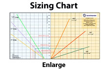
The Sizing Chart is a handy chart for use with low pressure applications most often associated with atmospheric pressure fuel cells. To use this chart, determine the maximum flow rate (scfm or slpm) and approach temperature and pressure drop you need. The approach temperature is the difference between the fuel cell exhaust dew point temperature and the desired fuel cell inlet dew point temperature.
The Sizing Chart shows conditions for a 70°C fuel cell exhaust dew point and a 40 rpm wheel speed but it gives a good estimate for most fuel cell applications. It shows approach temperature achieved by various combinations of core diameter and length. The ordinates show approximate face velocity and pressure drops per side. This is approximate because it is very dependant on the size of pipe connections and the aerodynamic design of the manifolds. The abscissas show inlet air flow rate and approach temperature.
Enter the chart by marking your desired flow rate and drawing a vertical line there. This line will cross one or more of the core diameter lines. At each crossing point, trace a horizontal line over to the left side of the chart. There it will cross the three standard core length lines. At these crossings, trace another vertical line to the approach temperature scale.
You should have one or more solutions of core diameter and length to consider. Pick the one that gives you the desired approach temperature and pressure drop. You may also consider packaging dimensions for your specific application. Typically, practical solutions have a face velocity in the 500 to 1,000 fpm (2.5-5.0 m/s) range but any face velocity that yields the results you need is fine.
For high pressure applications the process is a little different. Figure 2-2 compares face velocity with delivery relative humidity (RH) referenced to the cathode operation temperature.

Calculate your maximum actual cubic feet per minute (acfm) and your desired RH at the stack inlet. The horizontal “RH” line should intersect the family of lines representing the various core lengths. At each intersection, note the “face velocity” on the abscissa.
Determine your face velocity for each cartridge size as follows:
Nominal Core Diameter |
Face area (ft2) |
Face velocity (fpm acfm ÷ face area ) |
4 |
0.0271 |
|
6 |
0.0528 |
|
8 |
0.1184 |
Table 2-1
Draw these face velocity lines on the chart below. Solutions exist where these vertical lines intersect one of the families of core length lines above the desired RH line. Thus you may have several diameter/length choices for your engine.
In both low and high pressure applications, it is possible to operate cartridges in parallel or series to achieve conditions outside those on the chart.
Next: Cartridge Details
How Humidicore™ Works
Picking the Right Size
Cartridge Details
Manifold Design
Motor Options
Leakage Considerations
Installation Considerations
Field Service

The Humidicore™ was recently selected as one of R&D Magazine's top 100 Most Technologically Significant Inventions of the Year.

